NOTE: This guide is based on V1.3 by “Fragmaster”. The original version by RC Hobbys UK and Fragmaster’s new V1.5 will go together a little bit differently. The main differences from V1.3 to V1.5 are swept-back boom tubes, bearingless arm joints, and a canopy that does not slope down to allow for bigger batteries.
The original files for this project can be bought here:
http://www.rchobbysuk.co.uk/store/p127/DJI_Inspired_%283D_Printable_Quad%29_STL_FILES.html
They were designed by RC Hobbys UK to be a 3D-printable version of the DJI Inspire One. They did a fair bit of work to create the files, so I urge anyone who wants to build this to buy the files.
After that, go here and read through this whole thread:
http://www.rcgroups.com/forums/showthread.php?t=2327044
Then, forgot all about the files you bought and piece together something from the random upgrades that people on the forum have contributed. Personally, I went with a collection of files that have been assembled and cleaned up by “Fragmaster”, what he is calling V1.3. I also made a few tweaks of my own, and used a few other parts from the forum. The thread for V1.3 can be found here: (EDIT: This has become the V1.5 post)
http://www.rcgroups.com/forums/showthread.php?t=2399740
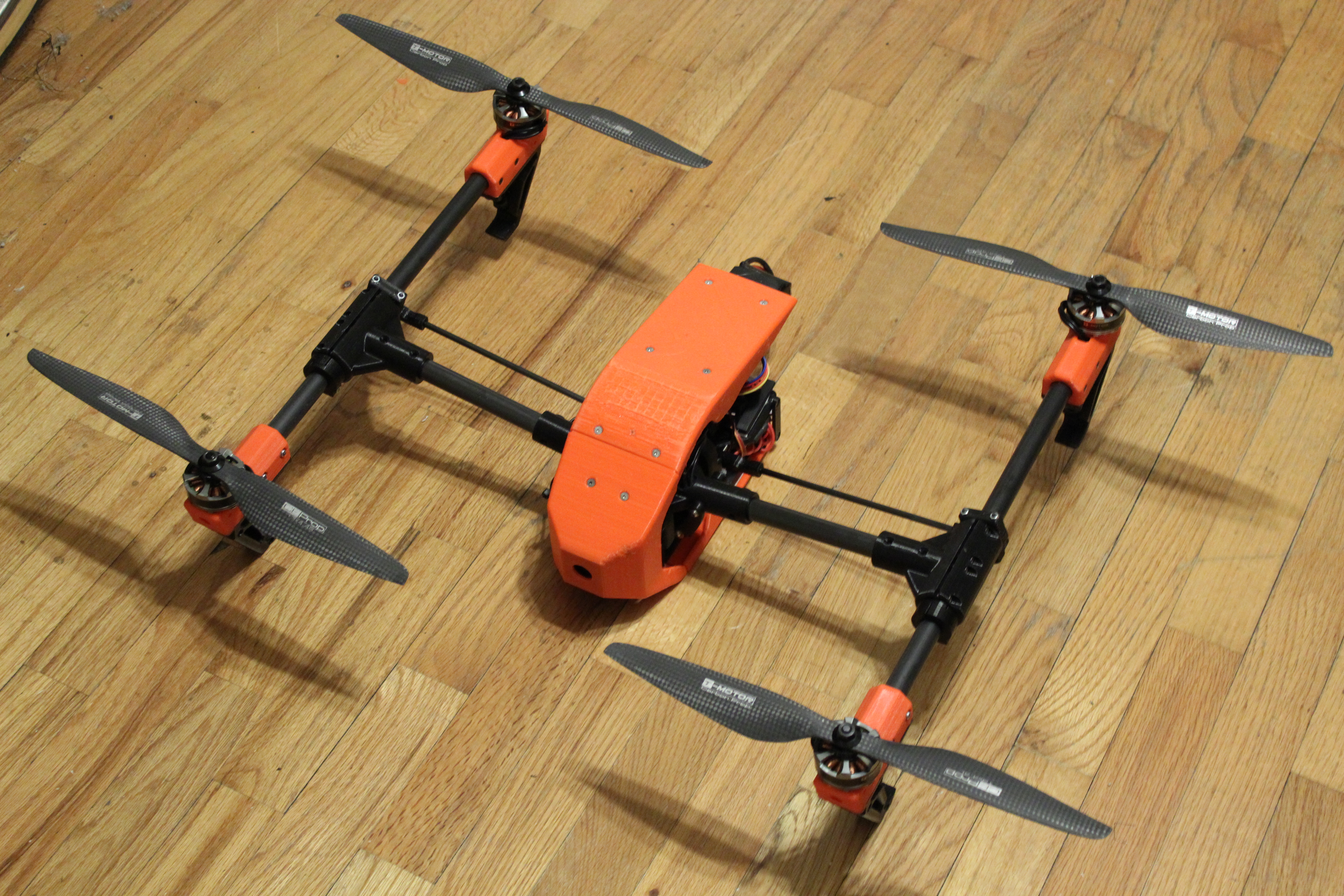
OK, on to the build pictures. Since this was my first time building this as well, I took some steps out of order and had to backtrack. As a result, the pictures that I post may have additions shown that have yet to be added according to these instructions. I’ll alert you when this is the case.
First, of course, you need to print the parts. I used PET because it does not warp nearly as much as ABS and it won’t get all soft and gooey in the sun like PLA. The downside is that PET is on the heavy side and is twice as expensive as the above mentioned plastics.
I printed all of my structural parts with 2mm skins (top and bottom layers) and 2mm shells. I used .2mm layer height for everything. It is important to use a thick shell setting so that you will be able to drill the holes larger to accommodate the brass inserts without getting into your infill. Plus it will make the parts more rigid.
The brass inserts that I used can be found here: http://www.mcmaster.com/#catalog/121/3303/=xc6jss (McMaster #94180A333)
To install them, drill the hole out with a 3/16″ drill bit. Then insert a very long m3 screw into the insert until it is flush with the bottom. Plug the insert into the hole, then heat the top of the brass insert with a soldering iron. You can press down a little on the screw as the insert melts its way down into the part. Once the top of the insert is flush (or slightly below) the part, remove the iron and hold the screw so that it is sticking straight up from the part until the plastic cools. Then unscrew the screw and continue with another insert.

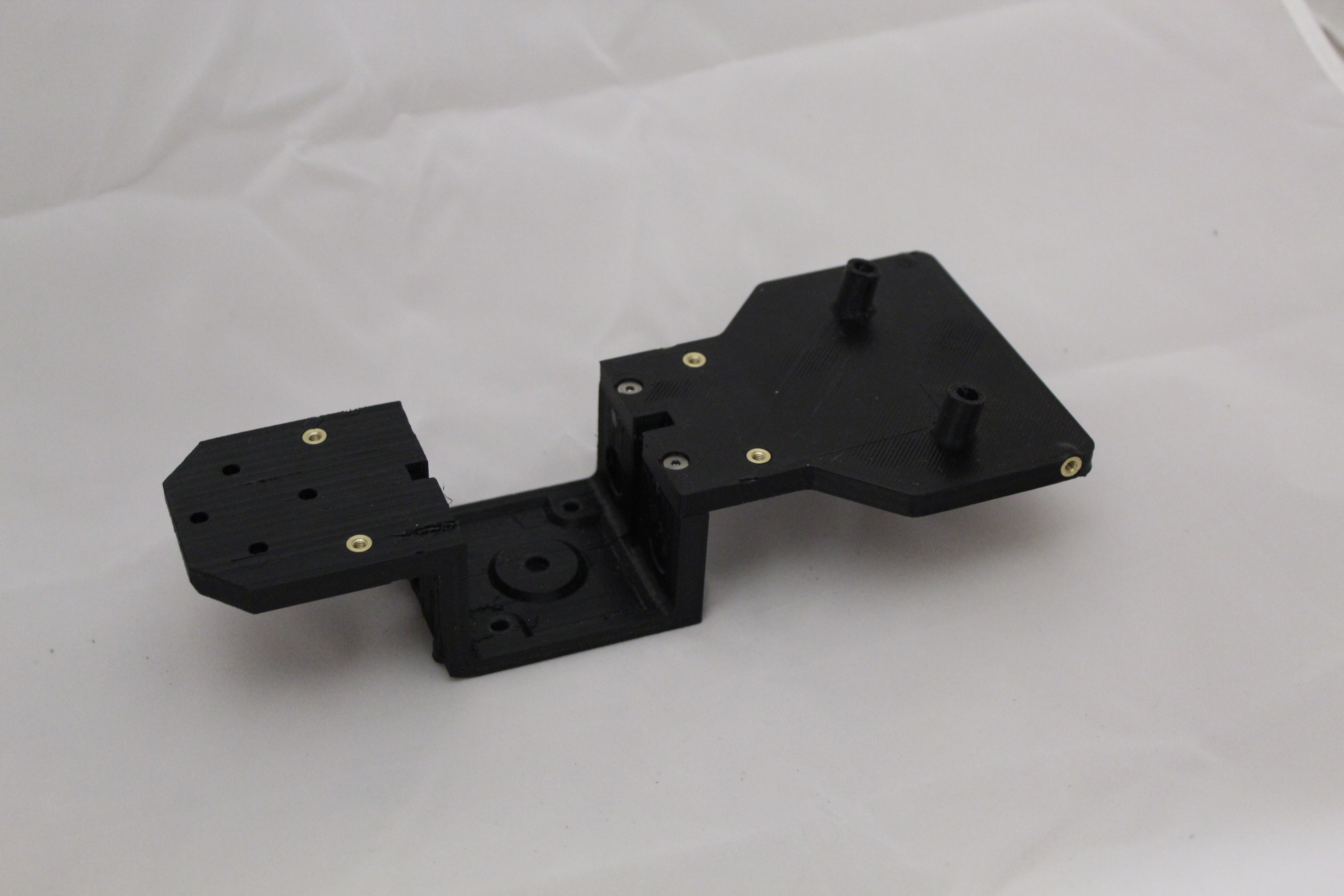
Frame Bottom Short and Frame Receiver Shelf were both printed with 20% infill. I only used 1mm skins for the shelf. Screw them together.
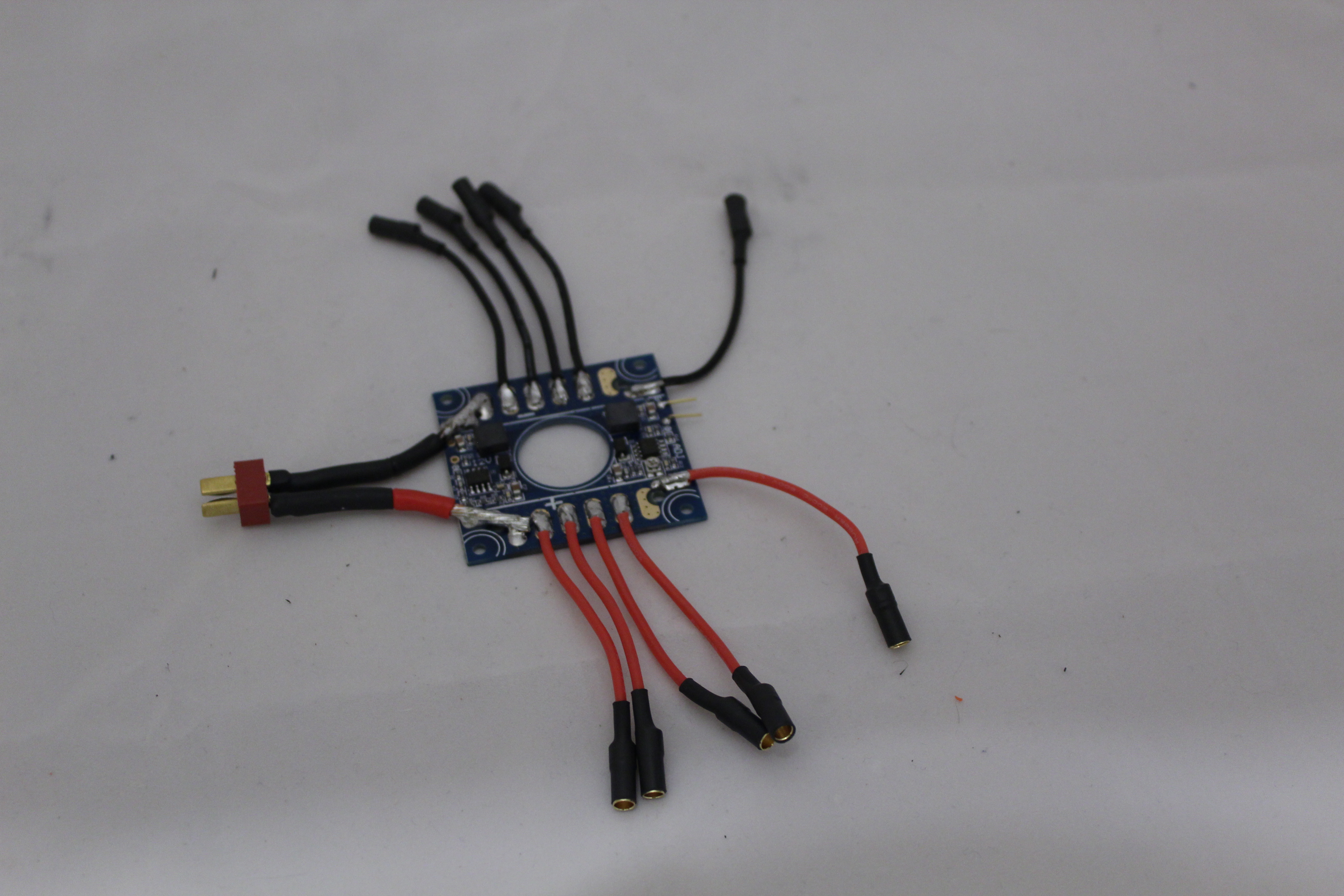

I used this distribution board and mounted it underneath the receiver shelf. This is one of those things I did not do until later, but should have done now. Note that I am using the variable voltage output of the board to power the lift servo. You’ll want to set a suitable voltage now.
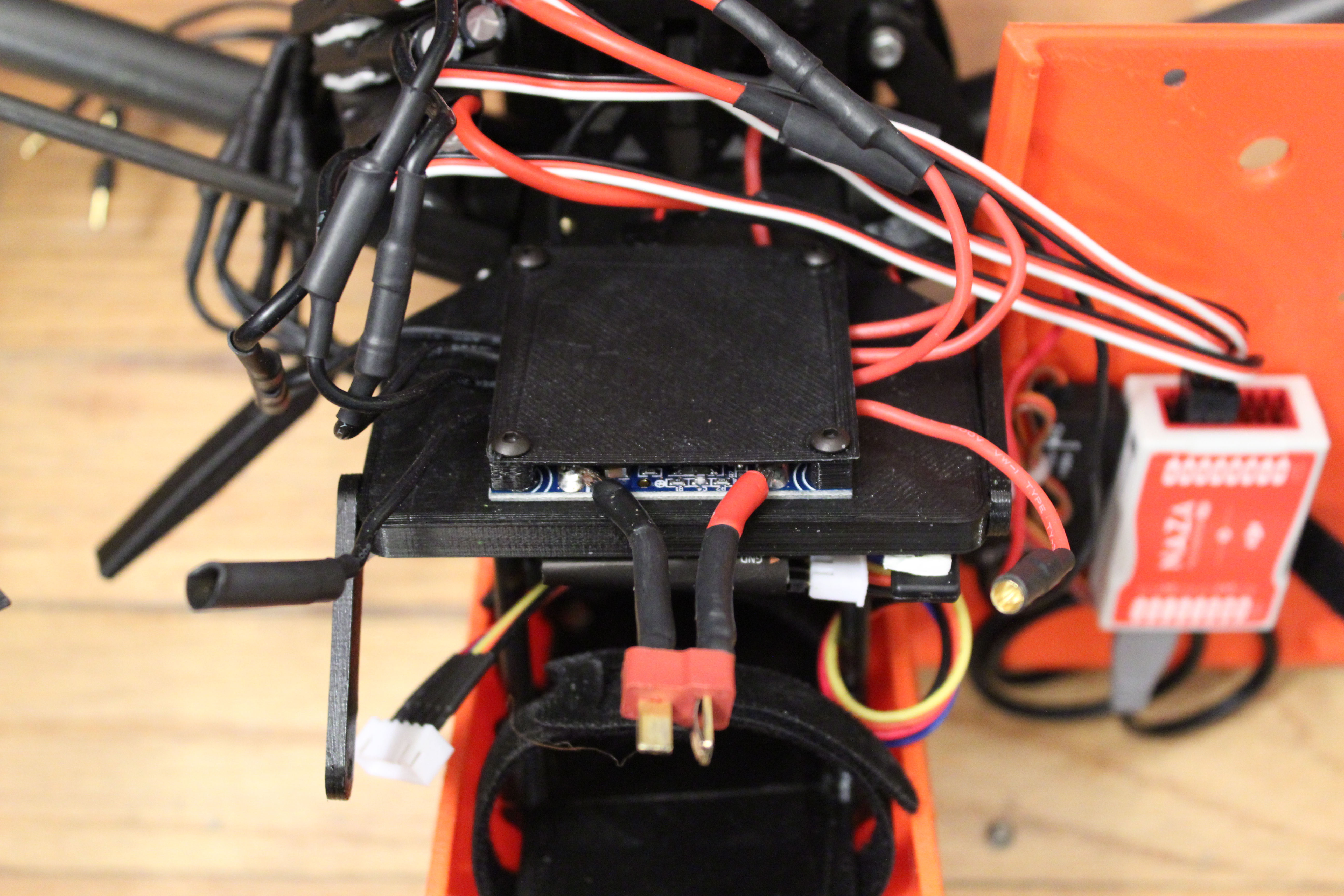
I also created a cover for the board to prevent shorts. STL here.
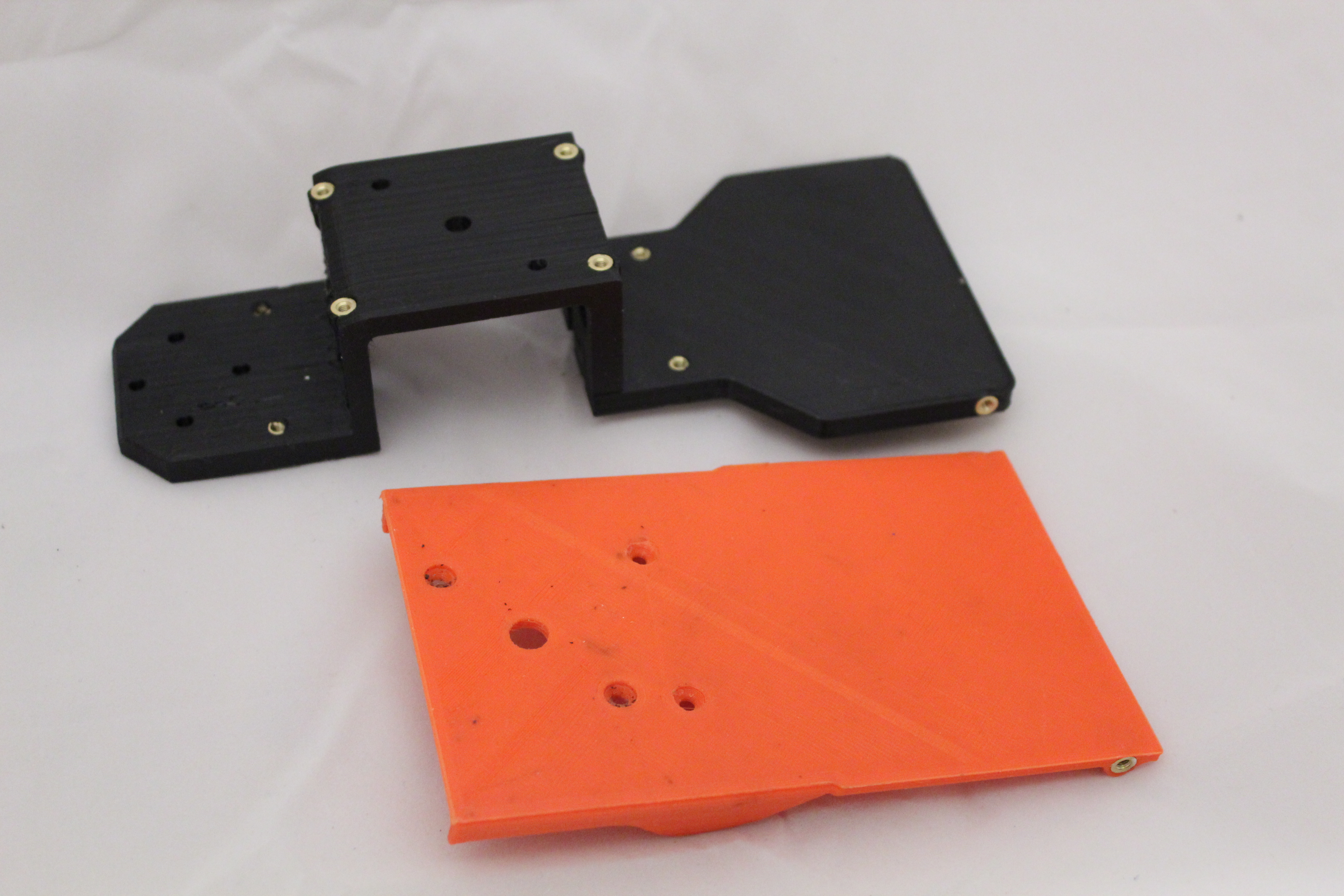
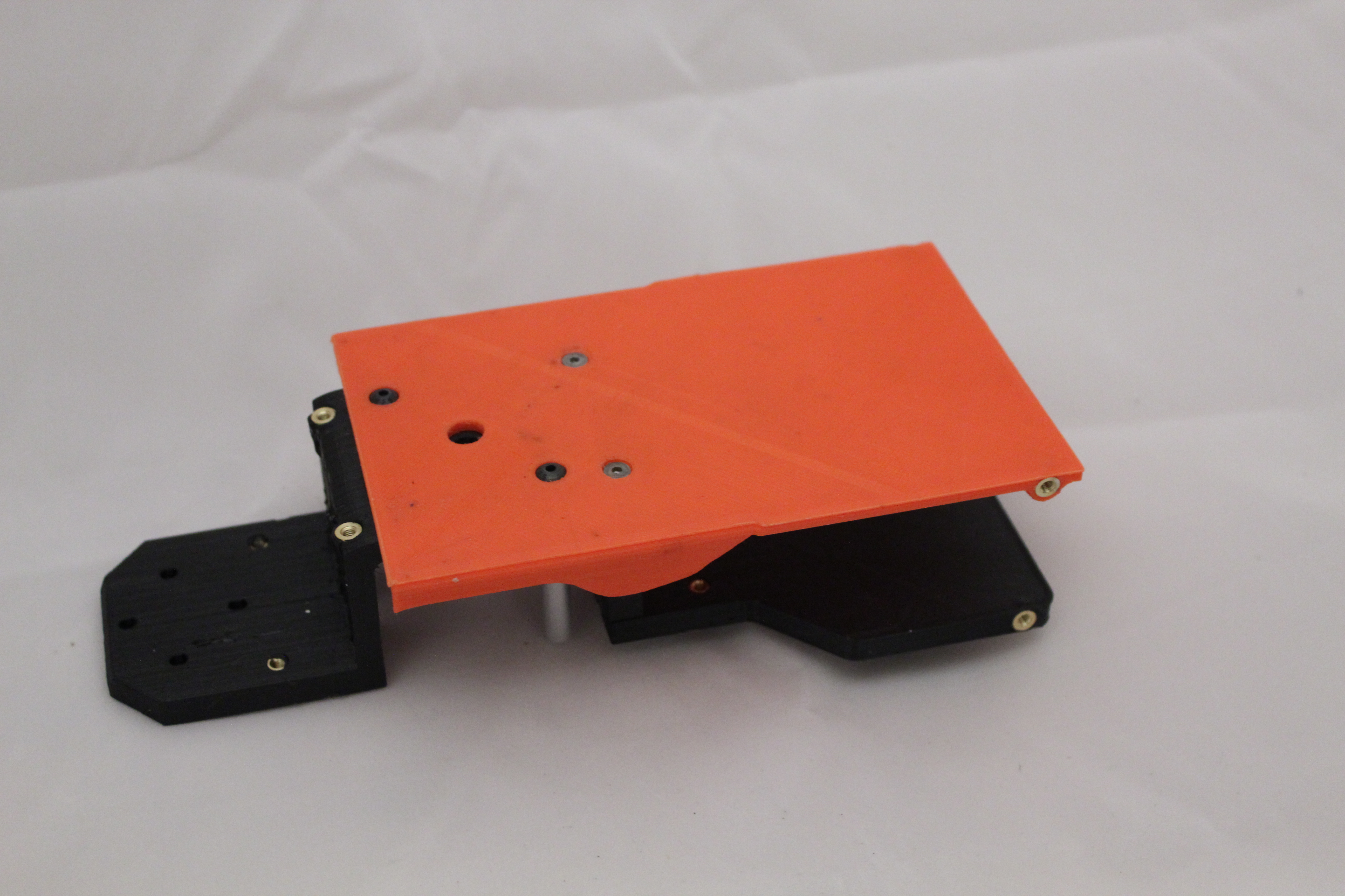
My Frame Bottom Plate was printed with 20% infill and 1mm skins. Screw it to the bottom of the frame. In the normal version, you would use four 3mm screws to secure it – two along the back side, and two in the diagonal holes. I use two 6-32 screws for the diagonal holes because I’m using a modified version of the wormdrive that uses two aluminum standoffs (1/4″ O.D., 1.5″ length) for added stability. I don’t actually recommend this mod, but if you want to try it, here is the STL for the wormdrive.
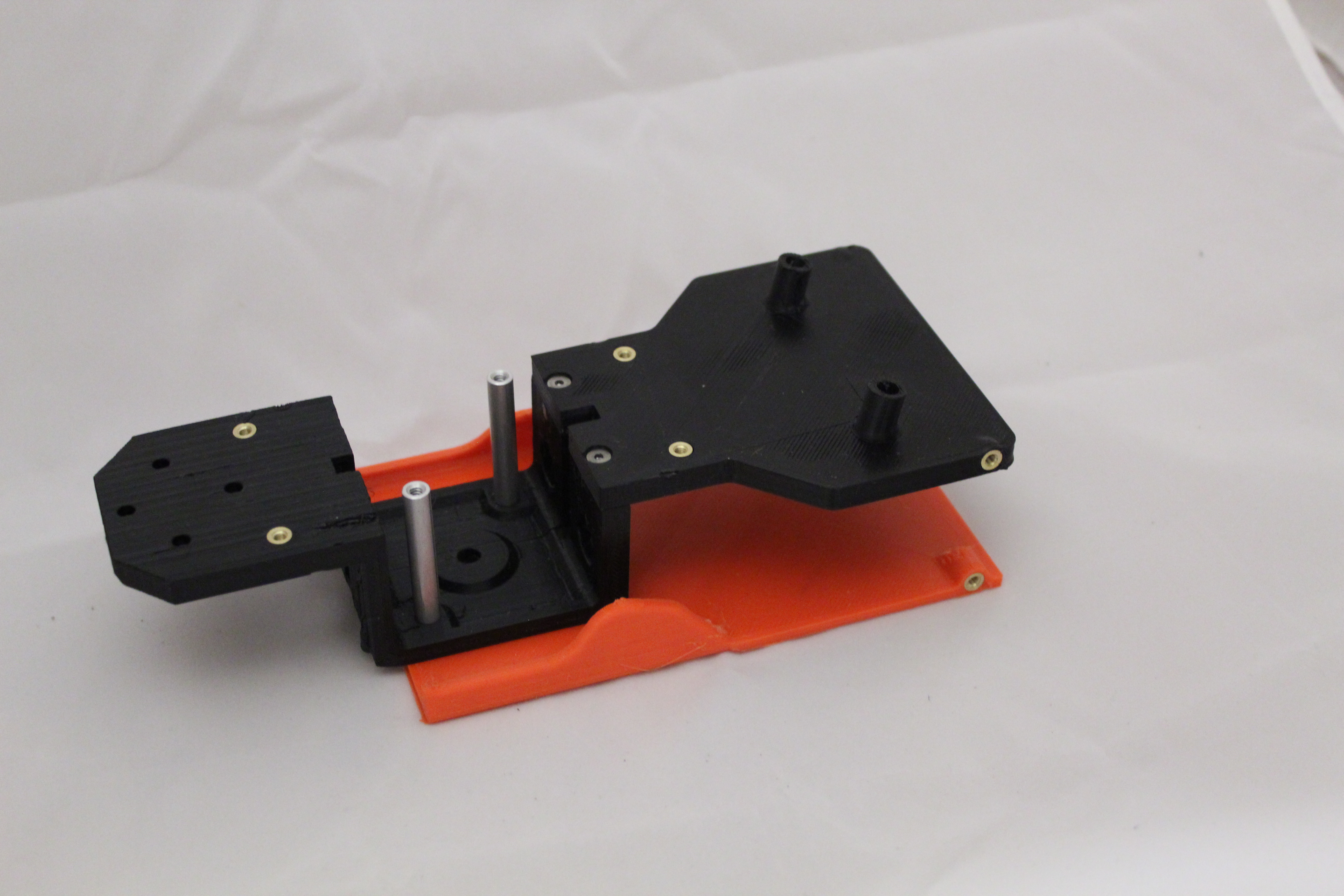

Add the two little Frame 38mm Struts. I printed mine solid.


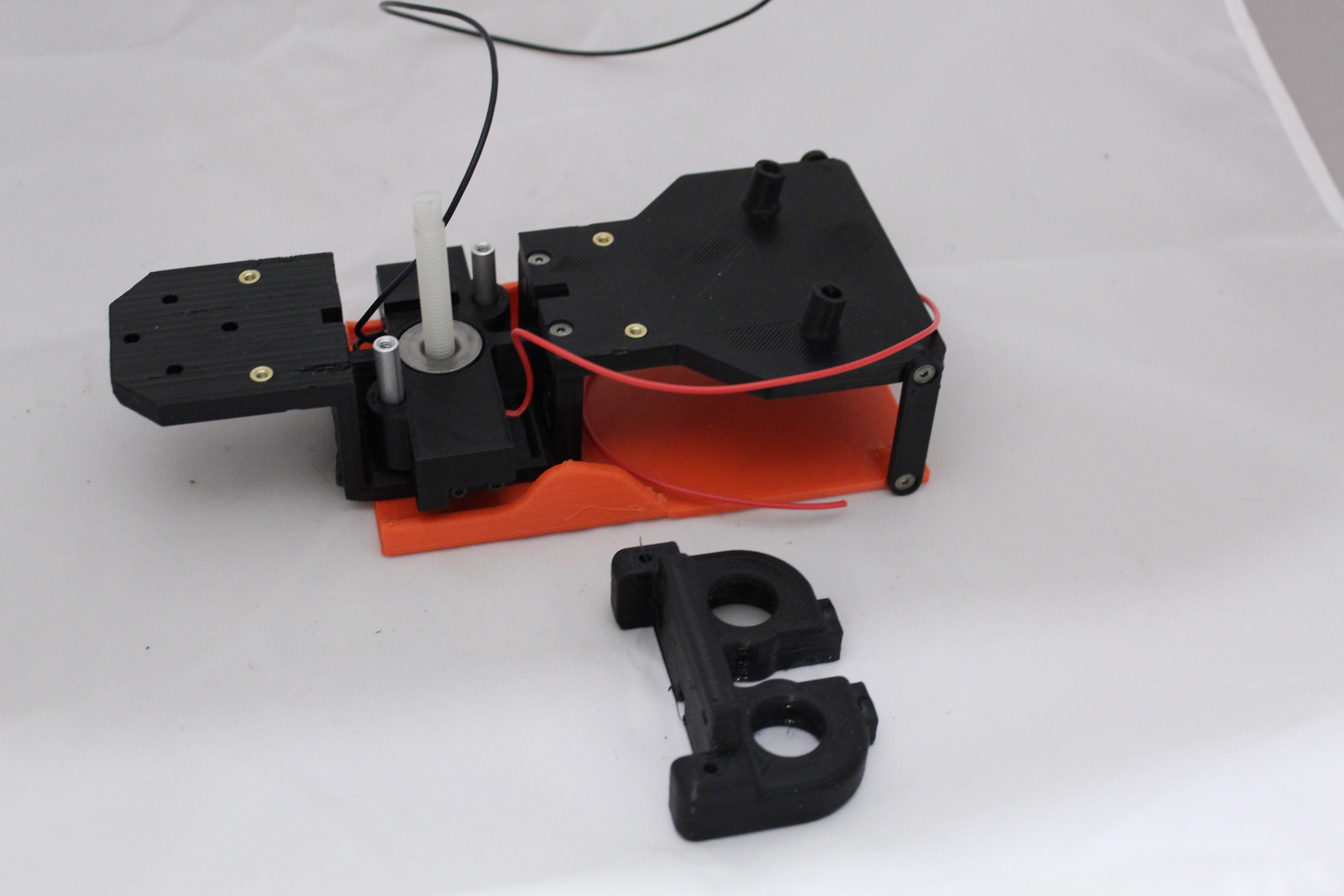
Install your limit switches and whatever captured nut you want to use into the Wormdrive (printed at 20% infill). My version uses a weld nut for an 8mm rod. Other options can be found in the forum linked above. Also, here is the wiring for the limit switches. This is for the version that does not use an Arduino to control the arms. I did not come up with this design. More info about it can be found scattered around the forum.
The basic idea of this method is that the limit switches are in series with each other and the servo motor so that if either of them trips, it will stop the servo. The diodes are installed parallel to each of the switches and allow current to flow through them when you flip the switch to move the mechanism in the other direction. Otherwise, once a switch had been activated, the mechanism would never move again.
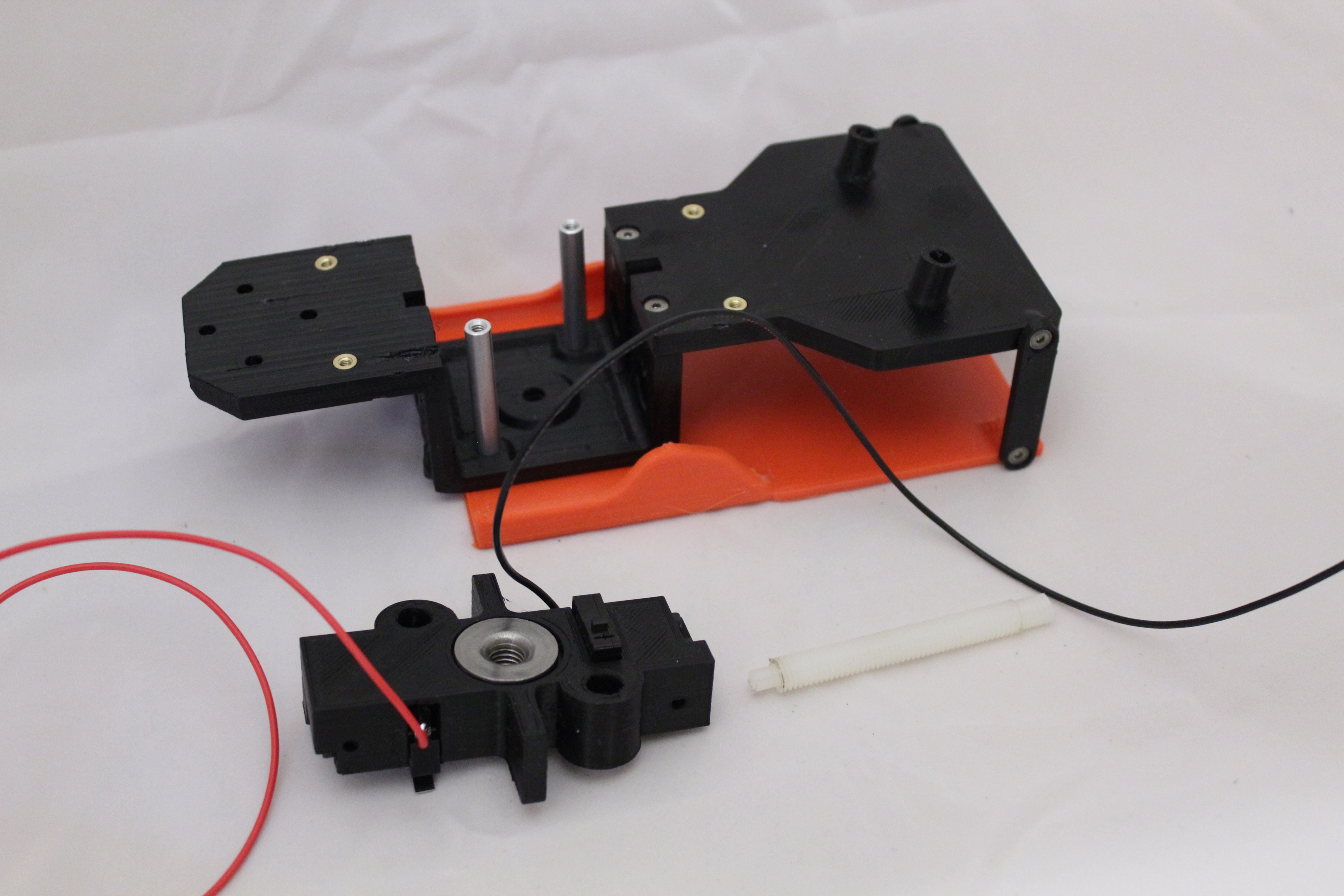

Run your threaded rod through the wormdrive. Check that your bottom switch activates against the bottom of the frame. I used a nylon rod for smooth action against the steel nut and to save some weight. Most people are using metal because they do nut have the aluminum rods to help keep the wormdrive from flopping around left-to-right. As you can see from the first picture, I used a lathe to turn down a small portion of the rod at the bottom so that it fits nicely inside the hole at the bottom of the frame. Others are using bearings and such. I did this because any force that pushes the arms down is going to be trying to push the rod out the bottom of the frame, which could rip the rod from the servo if it was left unsupported. Notice, also, that I notched the top of the rod to fit the notch in the servo horn adapter that I’m using.


Cut your 16mm tubes to length. Get them close to size and use sandpaper or a sanding belt to get them exact. Epoxy these boom tubes into the Frame Arm Joints and Frame Outer Arms. PRINT THESE PARTS SOLID. Don’t bother mucking around with the screws that go through the tubes to secure them. Believe me, It’s a stupid way to attach these and it will ultimately loosen up and/or break. Have you ever had a snow shovel that was put together like that? You broke it, didn’t you? See. It’s OK if you just dry fit them now if you are a wimp. Otherwise, glue them in place. Make sure the two T’s are completely level with each other. You can place them both down on a level surface to do this. Also, You’ll have to drill or grind out the excess tube that will partially block the exit holes for the motor wires.
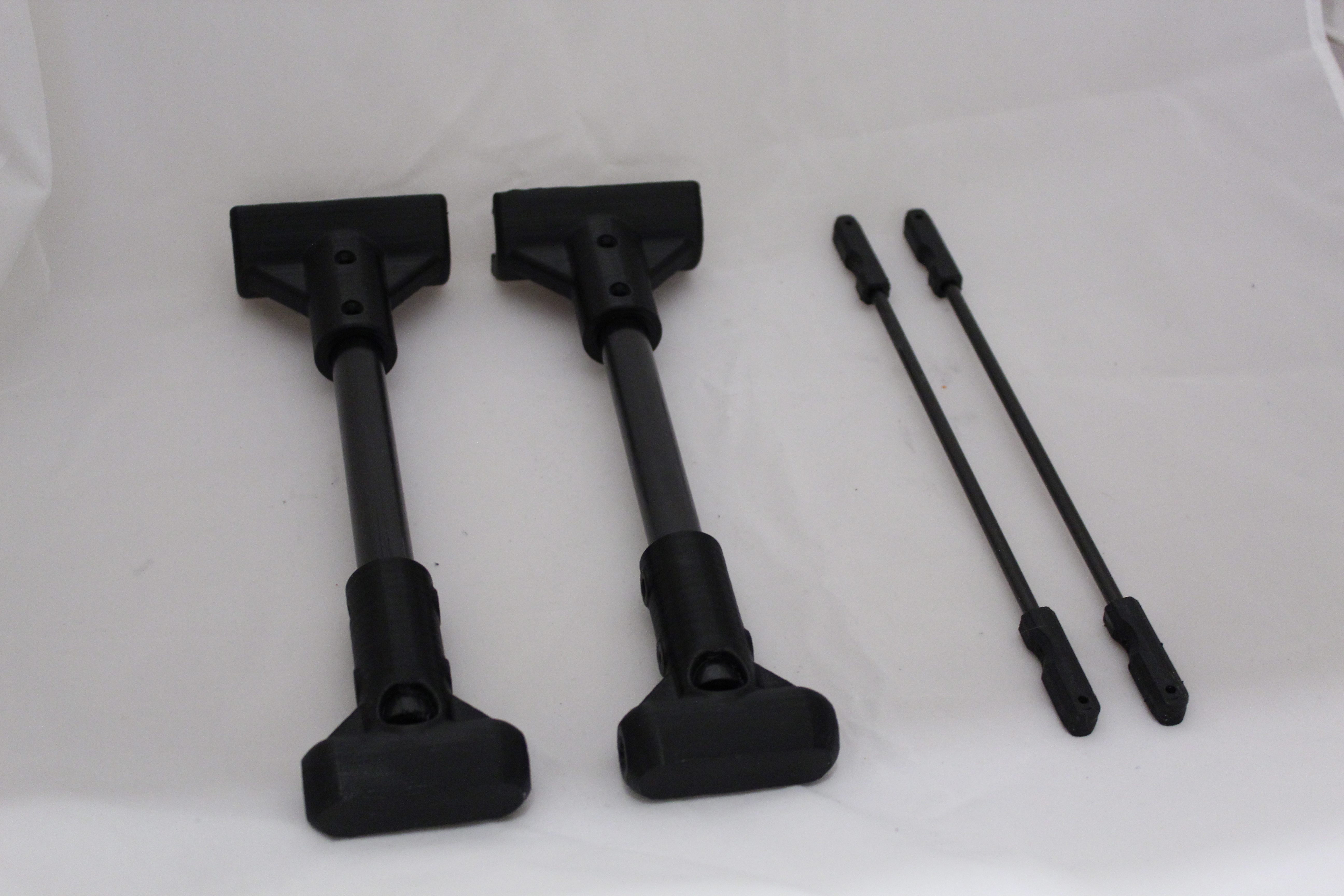
If you want to epoxy your rod linkages now, it might be a good idea since you already have some epoxy mixed up. The distance between the center of each mounting hole of the control rod should be exactly the same as the distance between the center of the two T joints. If you measure your tube and rod lengths perfectly, then it should all work out fine. Some people have used adjustable-length linkages here to fine tune things. If the lengths are off then the motors will not stay parallel when lifting and lowering.


Prep your booms by installing the 8mm aluminum or carbon fiber pivot tubes, and either 608zz bearings or nylon bushings (STL here.) I had to upscale the bushings slightly to get a good, snug fit inside the holders. You want a slop-free fit here. NOTE: If you are building V1.5, you will be using the printable bushings included in the STL package. They don’t have to be printed in nylon.


Attach the Frame Bearing Holder Rear. (The rear bearing holder is the one with the mounting points for the control rods.) Slide the boom assemblies in place. Slide the Frame Bearing Holder Front into place. I printed my bearing holders with 30% infill.


Prep your servo according to the diagram linked to earlier. (Note: do not use the servo in the pictures – it is too weak.) Also print out and attach your server-horn-to-rod adapter. You can find a link to it in the following post, which also shows a little more about modifying the server and putting together the lift mechanism:
http://www.rcgroups.com/forums/showpost.php?p=31101974
Install the servo and servo horn / rod adapter. I printed the Frame Main Body Top at 20% infill. Please note that I ran the screws the wrong way to mount the servo. You should install four brass inserts and run the screws from the top. Because I did this, I had to use lock nuts on the top side, and I had to countersink the two back holes to keep the screw heads from interfering with later assembly.
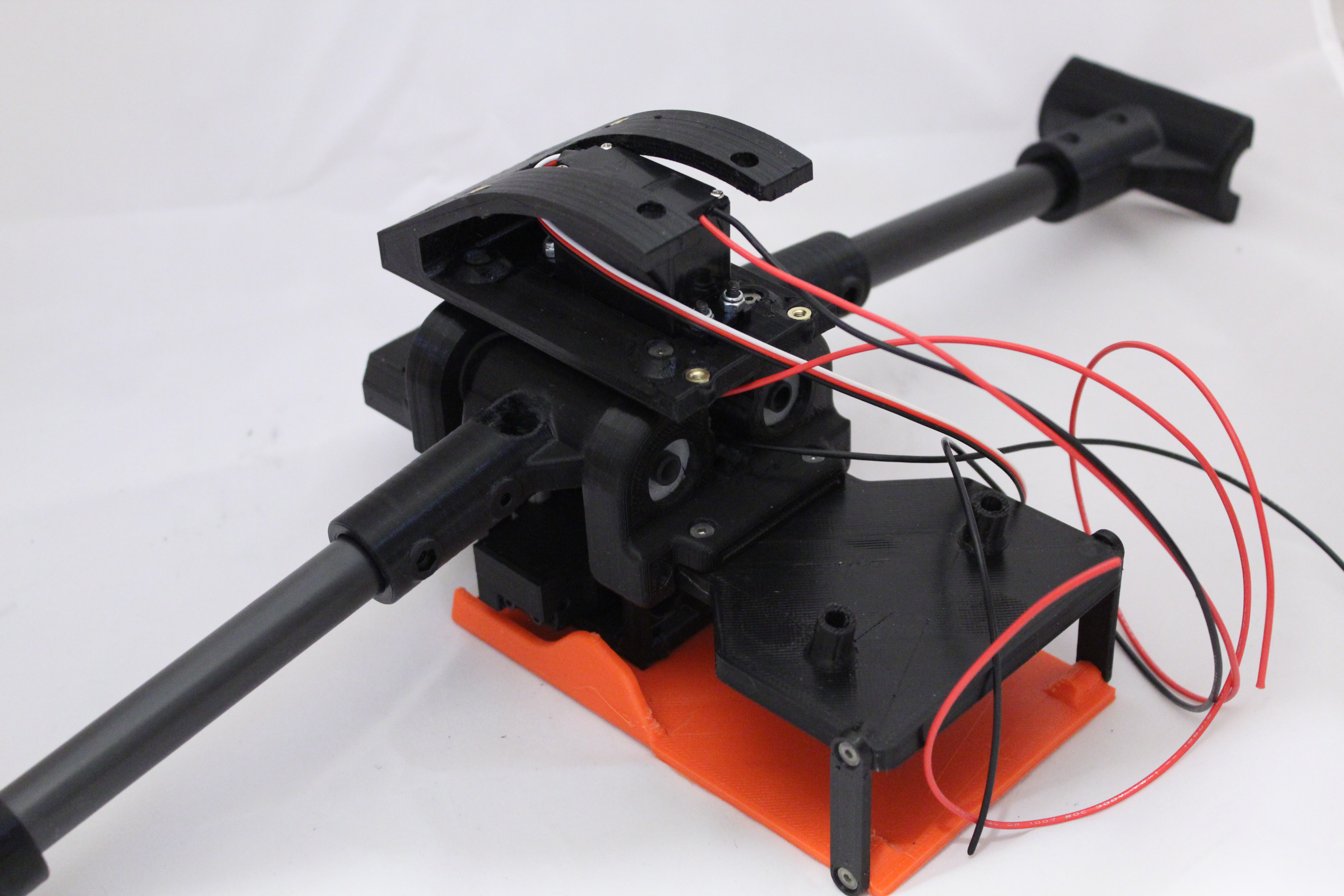
Attach the frame top to the two bearing holders.


You can tentatively install the Boom Lift Linkages (printed solid) to test the arm motion. You will have to remove the screws that run through the linkages and the arm joints later on to run the motor wires, so for now maybe just thread in a small screw through just the front pair of linkages. I used the electronics from my Discovery to actuate the server for testing.
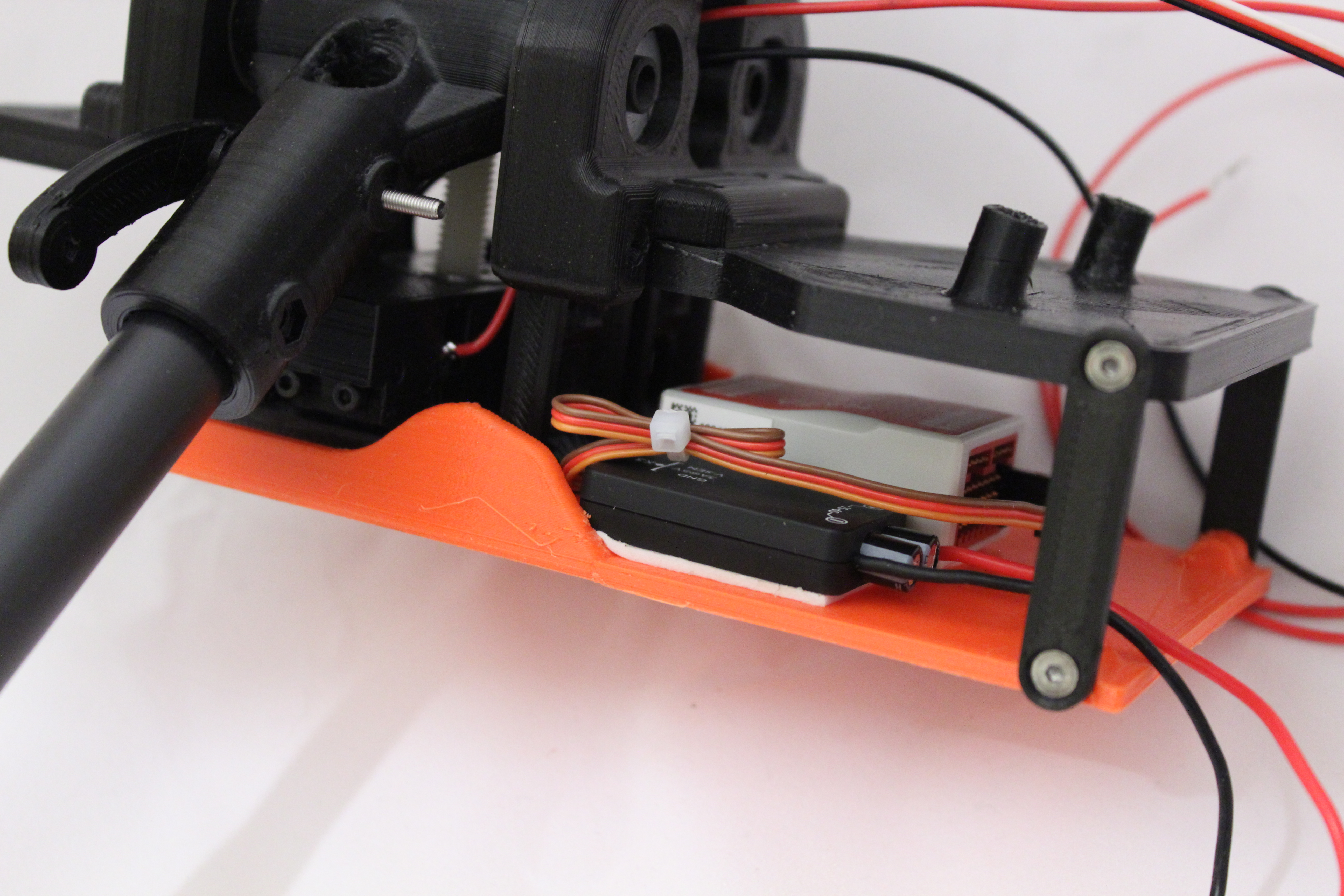
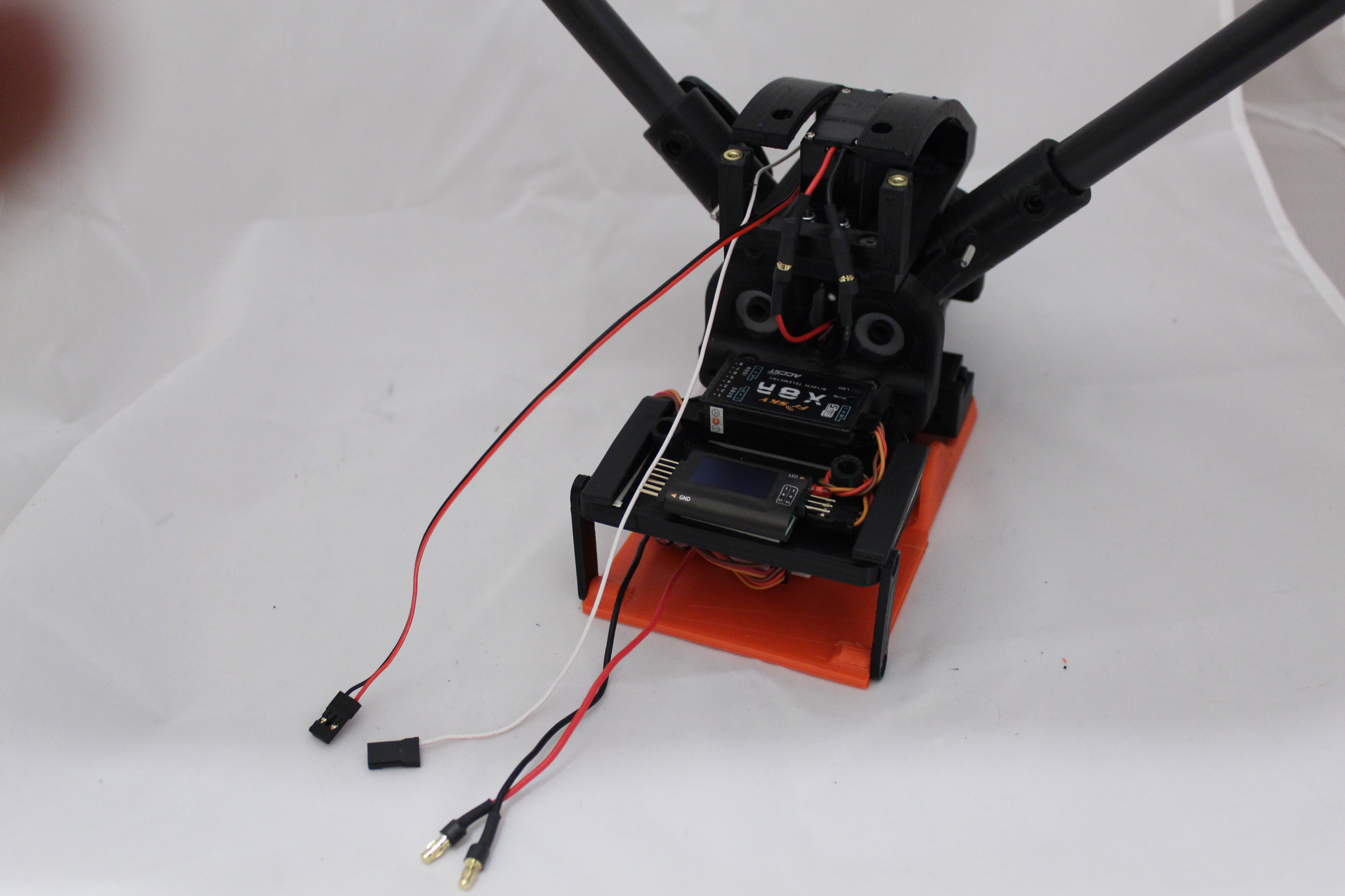
If you want to start installing your gear, now is as good a time as any. I mounted my NAZA in the center of the bottom shelf as far forward as I could get it. I mounted the power unit for it to the left of it. I also got really ambitious and stacked the four ESCs to the right of it (not shown). My receiver and voltage monitor are on the receiver shelf.
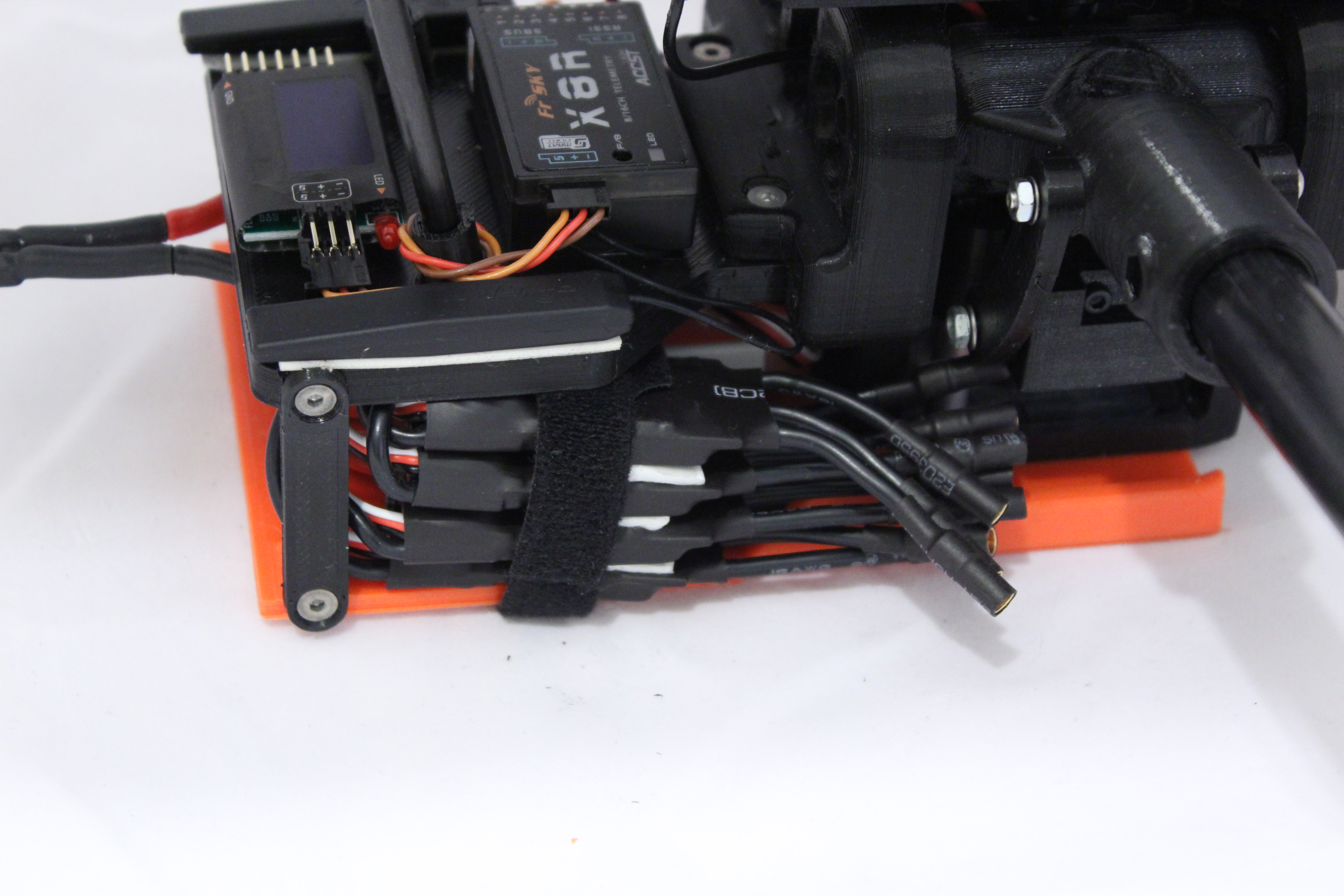
It was a tight squeeze to fit the four ESCs on the bottom shelf. I made a slot in the bottom shelf/plate and ran a Velcro strap around them all to hold them in place, along with some double-sided foam. Hey, it works.


You can install the Frame Strengthener and Canopy Tail now, which I think should be called the Frame Tail, but whatever. Note that in this picture I ran my servo wires through the frame strengthener. I later re-routed them to skirt around the left side of it because my battery was hitting these wires and connectors.


At this point I temporarily mounted my arm tubes and played around. With the battery in place and all the electronics (save the motors), I found the center of gravity, which for me was near the back of the rear bearing holder. I positioned my tubes to be centered with the center of gravity, which for me was 35mm back from the center of the boom tube. Please note that I am using 13″ props and they do not hit the boom tubes, but anything larger might. If you nose around the forum, some people have designed angled T junctions to angle the boom tubes backward to solve this problem (like the new V1.5). I decided to keep things simple and just shift the arm tubes back a bit. To each his own. I do feel it is important to try to keep your center of gravity in the center of the motors so that some of the motors are not working harder than others to keep the craft level.


Mount your motors on the motor mounts (printed with 30% infill). Before you run the wires down inside the mounts, you may want to dry fit this assembly and verify that when the props are installed and the arms are mounted in a position for the best center of gravity, that the props do not hit the boom tubes in either up or down position. Then, disassemble and grind an opening in your arm tubes at the location you identified to give you an even center of gravity. I used a small grinder wheel in a drill in the orientation shown in the picture below.

Run your motor wires through the motor mounts. I’m using a modified version of the mount that I found on the forum that has an access hole behind the motor. This gave me a bit more length on my wires, and even still I had to extend the wires from one of the motors.
Note, some people are mounting their ESCs below the motor mounts. You can find a few variations of these ESC boxes in the forum.
Slide two nylon bushings onto each rod if you are using them. NOTE: These bushings are not required for V1.5, and optional for the original and V1.3.
I say again, SLIDE ON THE NYLON BUSHINGS. You don’t want to forget these, especially if you glue your motor mounts in place.
OK, now run the wires down the tube and out the hole. The hole should be large enough (or long enough) so that as the arm rotates when the boom raises up and down, the wires do not get pinched in the joint. There are scientific ways of going about this. I eyeballed it. You should now cover your wires where they exit the tube with something to protect them, be it heatshrink, rubber tubing, tape, or whatever. Just in case, you know.
Make sure that you have the hole orientated how you want it and then glue the motor mounts in place. Forget what you see in the pictures. The damn bolts are nothing but trouble. Remember that broken snow shovel! As of this writing, a few of us are tinkering with a version of the motor mounts that are split so that as one tightens down the bolts, the plastic will grip the tubes better. V1.5 includes this type of mount and some are reporting success with it. I say damn it all and just glue them in place! Again, make sure the two motor mounts are together on a level surface and the hole in the tube is aligned properly.
If you are thick-headed and use the bolts, make sure to poke something through the holes first to verify that you are not about to screw through your motor wires. See – another reason to just glue them on!

Run the wires through the boom tubes and bolt together the outer arm T joint thingies. Tighten all the bolts a little at a time until the arm tube is held firmly but can still rotate relatively easily. You probably don’t want to tighten these all the way down, especially if you added the nylon bushings. Be careful when handling the craft not to allow the arms to rotate too much and stress your motor wires. Also, it might make sense to tape or mark one of the groups of motor wires so that you can tell them apart later, although if you shifted the mounting location like I did, then one set of motor wires will be shorter than the other. Also, you will most likely have to remove the bolts that attach the boom lift linkages to the frame arm joints to allow the motor wires to pass unobstructed through the boom tubes. When reinstalling the bolts, first push something through the holes (like your socket driver) to check that the wires are not in the way.


Attach the Boom Stop Ring, Boom Support Linkage, and the control rod (all parts printed 100%). Before attaching the boom support linkage, I advise you to sand the shine down on the surface of the arm tube where it will mount. I would also draw horizontal lines with CA (super glue) and let them dry. You want to add extra friction so that the support linkage can really grip the tube well. I also urge you to install a second one (as shown in the second picture).

Assemble and attach your feet. Note that the tube sticks out a little bit and will insert into the motor mount. Sand it down as needed.
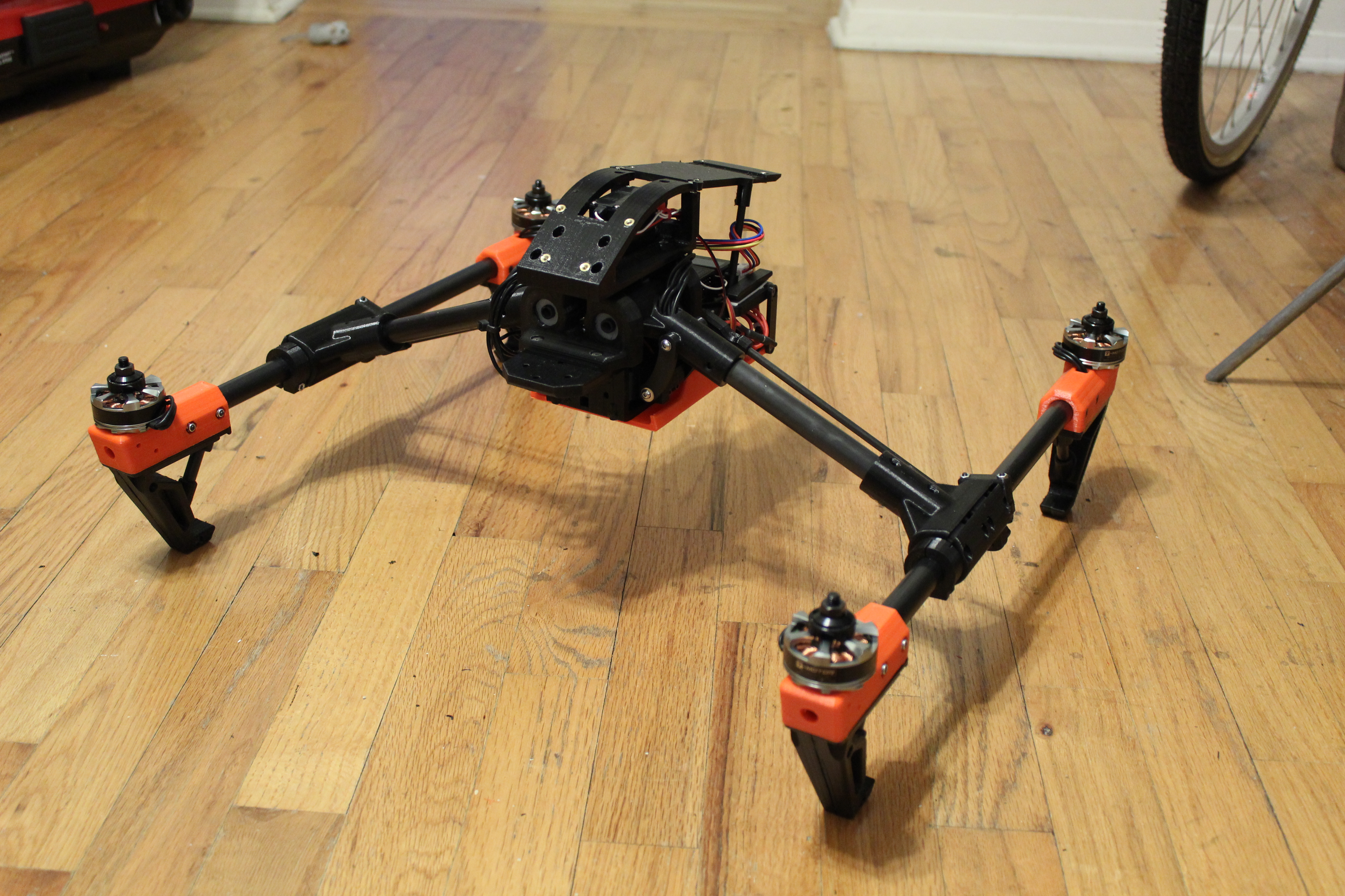
So far, things should look something like this. Actuate the arms up and down to ensure that the operation is relatively smooth and the motors stay level. If they do not, then either your control rods are not quite the right size, or you have too much slop. I found that the bushings that I had installed to replace the 608 bearings were a little too loose in the holders, and that actually introduced slop in the arm rotation, causing the motors to not be level when I lifted the arms. Replacing the bushings with better fitting ones actually solved this issue.
Well, you are pretty much home and dry now.
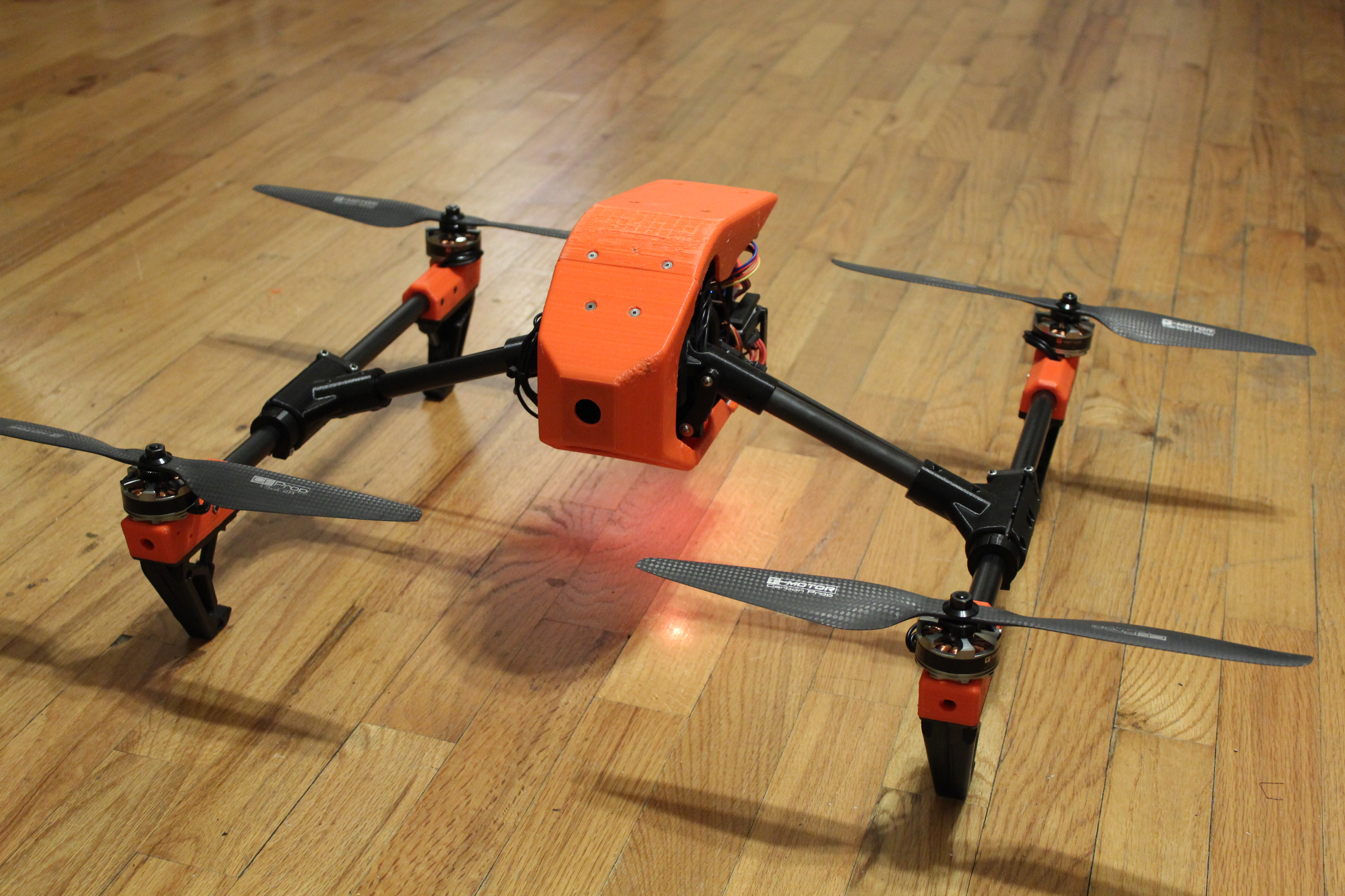
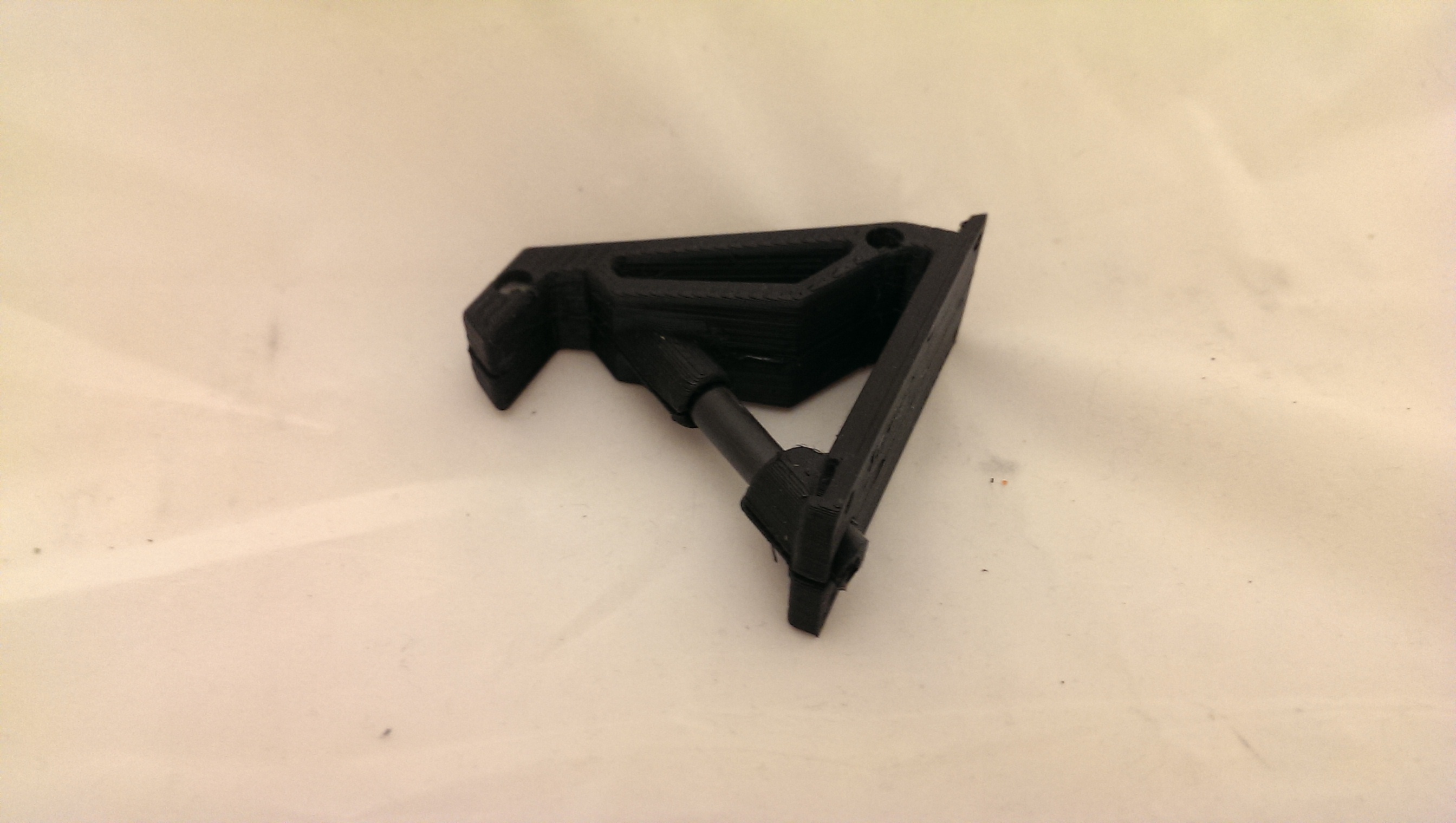
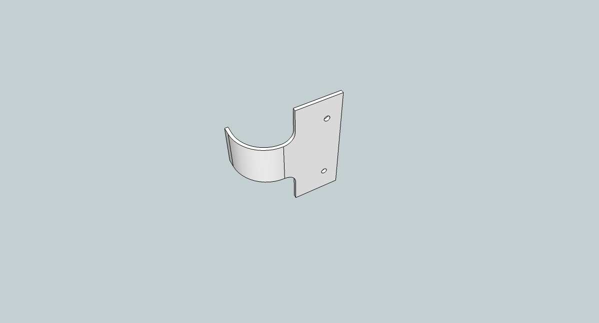
Install your Canopy Nose and Canopy Top. You can print these as flimsy as you dare. I only did 10% fill. They are massively heavy even still. You’ll want to install one or two Velcro straps on the canopy (actually frame) tail before installing the canopy top so you will have something to hold the battery in place. You will probably also want to install Velcro under the frame tail and on your batteries. Personally, I made a clip instead:

Now you’ll want to wire everything up. Good luck. Things will be quite tight if you installed the speed controls on the main frame like I did. I also ended up adding a GPS antenna mount, which you can find here:
http://www.rcgroups.com/forums/showpost.php?p=31441577
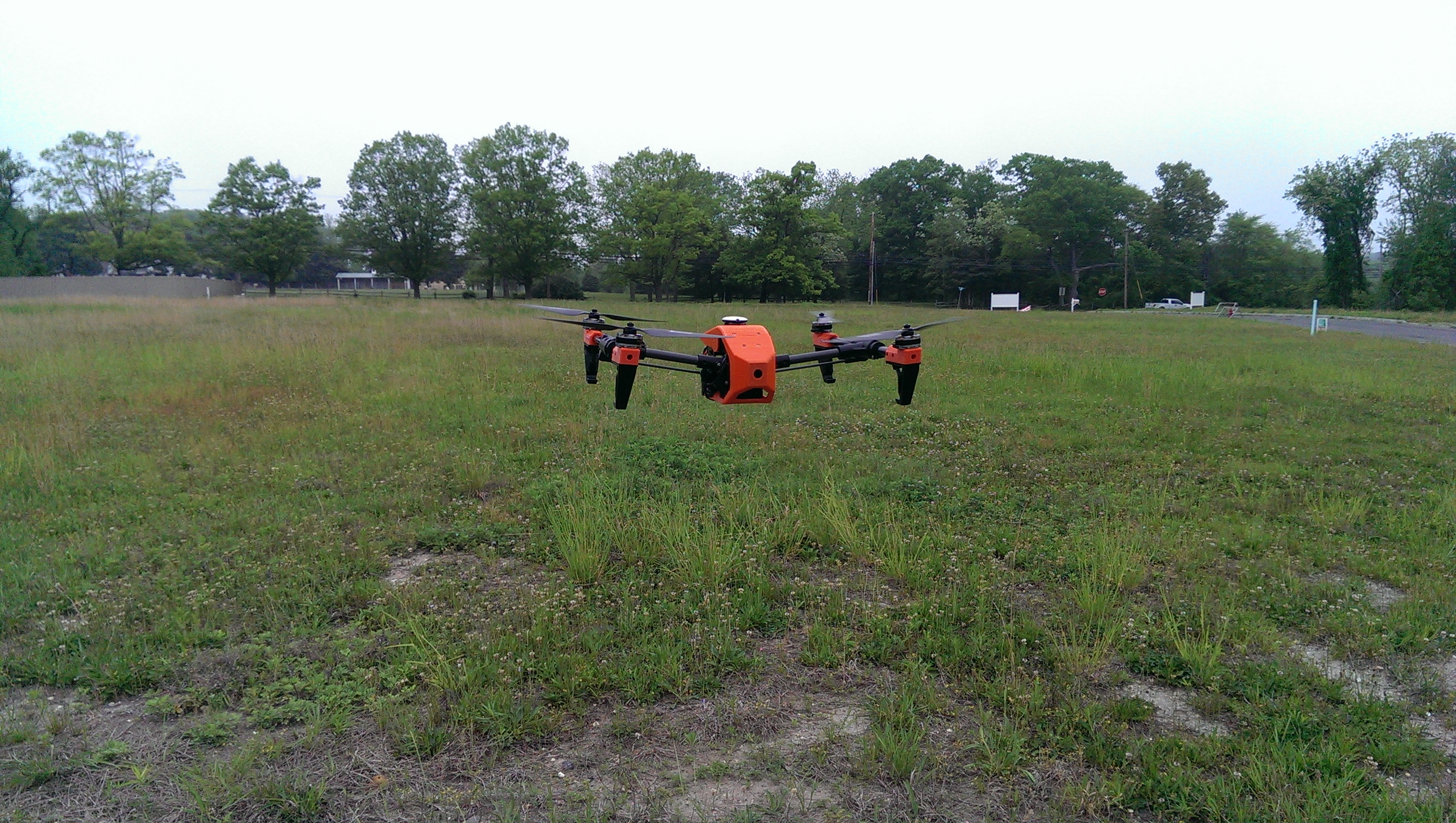
Now fly it!

I hope this guide helped you. I’m sure I missed some things, but you will figure it out as you print and handle the parts. No worries. Happy building, and happy flying!
I still dint get, how you fixed the servo motor for tilting the motor legs.
If u used an Arduino, then can u pls send the code.
If any other method can u pls explain again cz I couldn’t understand in both the places, i.e., in the forum as well as your website
Hmm, it’s been a while since I built this. In fact, I no longer have this quad at all. As such, I’m not sure I can explain the servo wiring any better than I did in the article. I did not use an arduino, I used the simple method with two diodes. Unfortunately, while simple, it is hard to explain in words and I do not have pictures. all I can do is refer you again to this section in the article:
—–
“Also, here is the wiring for the limit switches. This is for the version that does not use an Arduino to control the arms. I did not come up with this design. More info about it can be found scattered around the forum.
The basic idea of this method is that the limit switches are in series with each other and the servo motor so that if either of them trips, it will stop the servo. The diodes are installed parallel to each of the switches and allow current to flow through them when you flip the switch to move the mechanism in the other direction. Otherwise, once a switch had been activated, the mechanism would never move again.”
—–
So, as you see, basically you are cutting one of the wires that goes to the servo motor and splicing in both limit switches in series (using the Normally Closed contacts). This by itself would work to limit the travel of the lift mechanism since the motor would stop as soon as either limit switch was tripped. The problem is that then the motor would never move again since the circuit was broken. The diodes are installed in parallel across the two switch. Diodes only let electricity flow through them in one direction (the direction of the arrow from positive to negative). You have to install them so that they are conducting when the motor is traveling away from the switch, but blocking while it is heading toward the switch.
If none of that makes sense, perhaps you can go the arduino route, but you would have to track down the code on the forum since I do not have it.
Cheers!